Led Cube is a relatively interesting gadget that can surprise many guests. This is a toy consisting of RGB LEDs that can be individually programmed to give a very spectacular visual effects. In this article will be shown how to create such toy yourself using mostly 64 RGB LEDs and a microcontroller.
Below we can see an example Led Cube 4x4x4 in action:
httpss://www.youtube.com/watch?v=lNyc4WDKYAw
And here as a curiosity Led Cube size 16x16x16:
httpss://www.youtube.com/watch?v=n4LAJfLYdmE
So let’s begin constructing, we will need the following components:
1 x atmega 328P-PU
64x RGB diods with common catode
1x 18650 batery
2x 22nf capacitator
1x 16 MHz Crystal
1x solderless breadboard
Silver wire/jewelry wire with a diameter up to 1mm (I recommend a little less, eg 0.8 mm)
Some wires
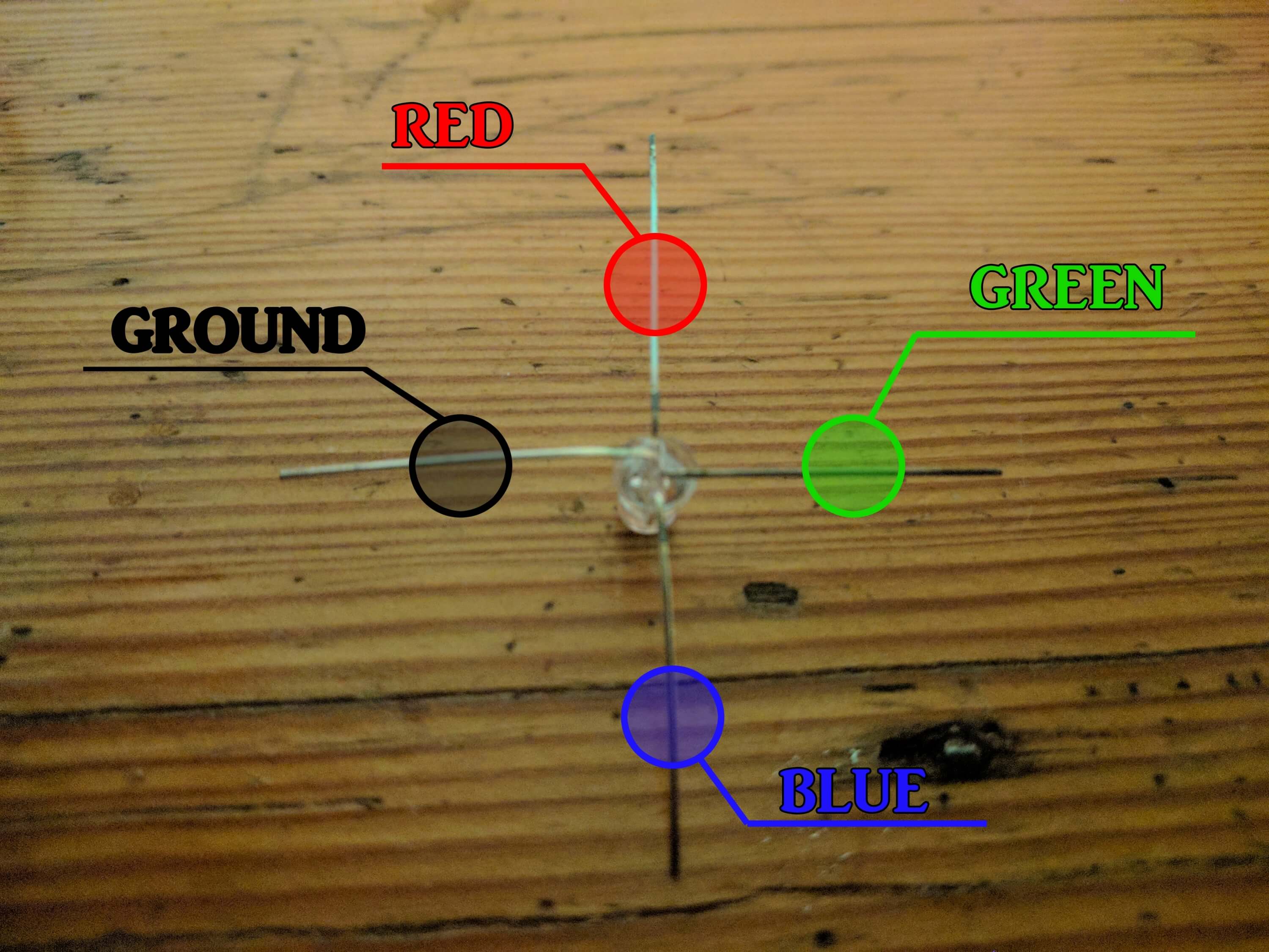
Our work begin with construction of 16 towers. Each of them will have 4 RGB LEDs. To prepare every led light each of the RGB feets needed to be bend at an angle of 90°, 180°, 270°, 360° according to the following photo:
So prepared diodes we put at an equal distance from each other, each rotated 90°. It is worth to prepare a template. Such template could be made from conventional carton, eg. after tea. For me, the distance between the LEDs is 25 mm, but this is a value that we can safely change according to our liking.

We cut four pieces of silver wire of equal length. Each of these pieces we straighten. The straigh they will be the visual effect will be better. This process is extremely difficult to do only with our hands so we should use other methods. Personally, I think that the easiest option is to use drill, as in the following video:
httpss://www.youtube.com/watch?v=ewuHD6RJFdE
We solder each wire with all four feets of RGB LEDs. Excess amount of wire we cut off. We should build more or less tower such as in the picture below.
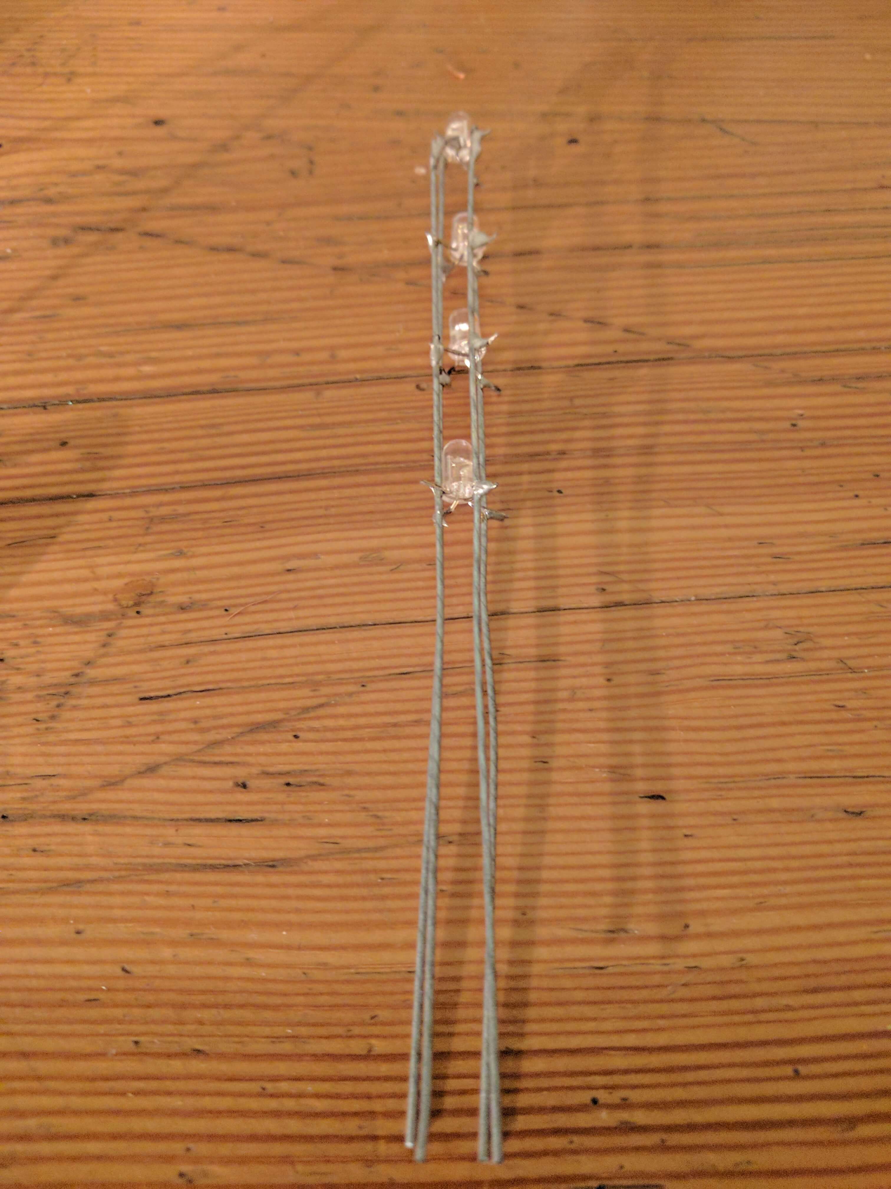
Carefully check with multimiter if all LEDs are working corectlly and are directed in the right direction, this process need to be repeated 15 more times.
This process can be quite monotonous and can take us a long time. Nevertheless, let’s do it carefully because later repairing anything will be much more difficult.
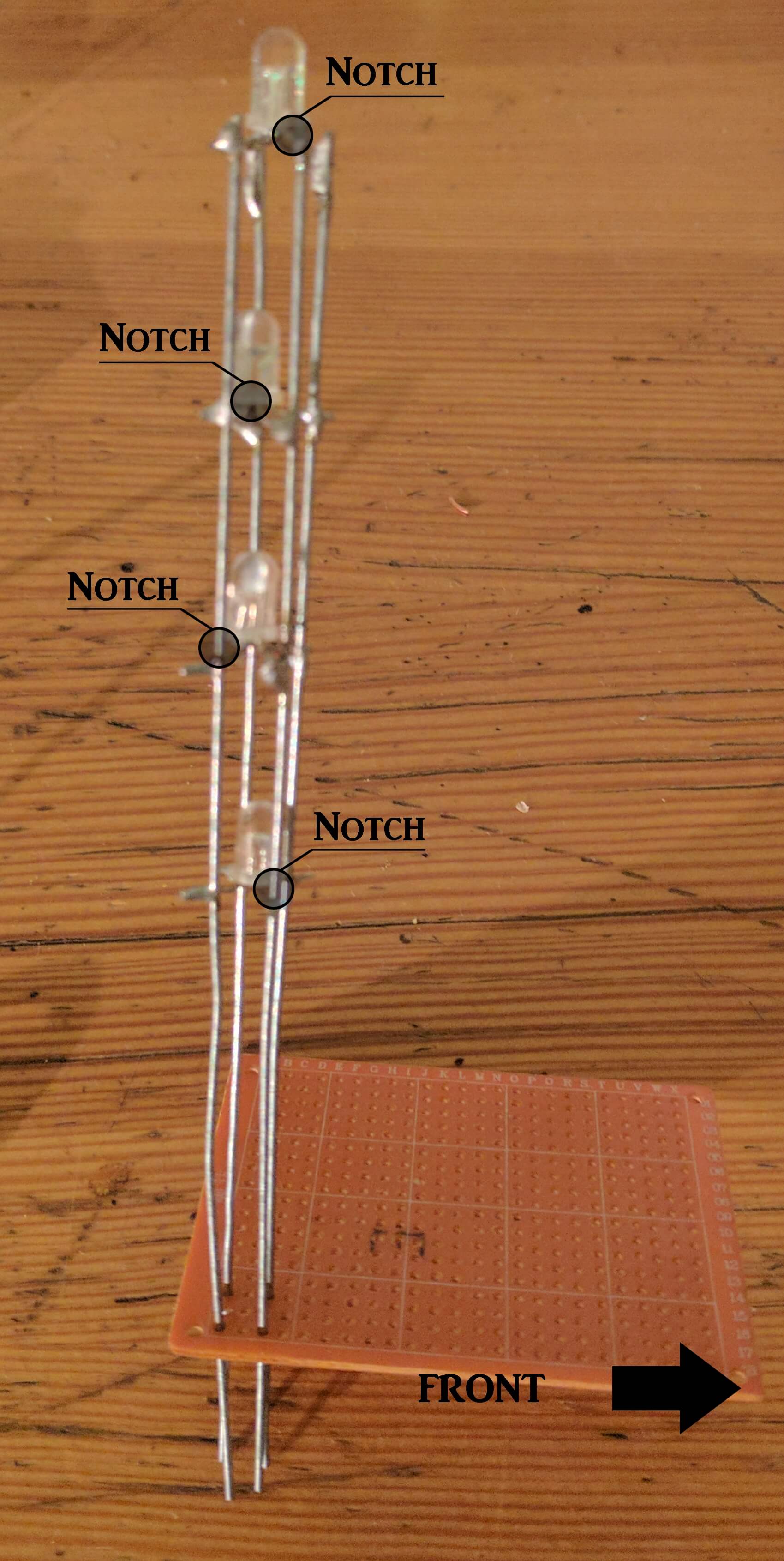
We have created basic components of our led Cuba now we have to move them to solderless breadboard. Every towers move through holes in the solderless breadboard and solder them. We must however, keep in mind that all the towers must be turned in the same direction. It is best if they are all directed so that the lowest rgb notch was directed toward the right upper leg, a second notch of the bottom diode has been directed toward the right lower leg, the third LED notch from the bottom of the tower should be directed toward the left lower leg. If you have a problem you can apply ground to the lower left leg, and power to any other leg. It should light 2 LED from the top. The following photo is showing how it should look like:
However, the most important is that all the towers were turned in the same direction, if the direction will be different from that shown above we will be able to fix it in the software. For a good visual effect we spread the towers at equal distances from each other. For ease we mark places where towers should be with pen. Let also try to make this Towers equal height. You should get something like this:

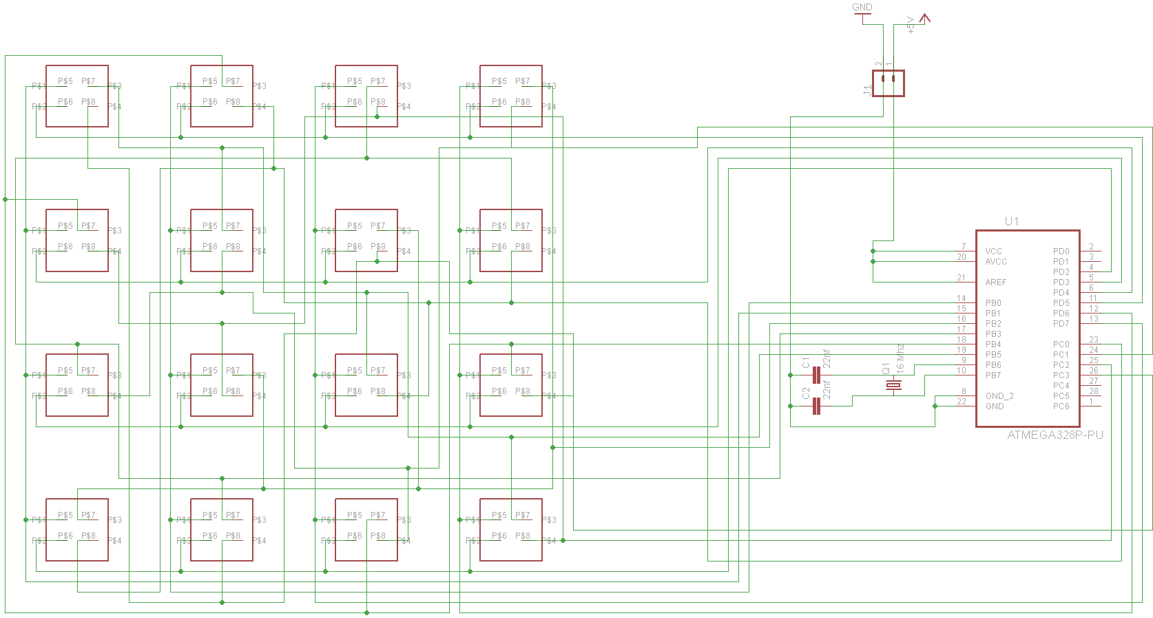
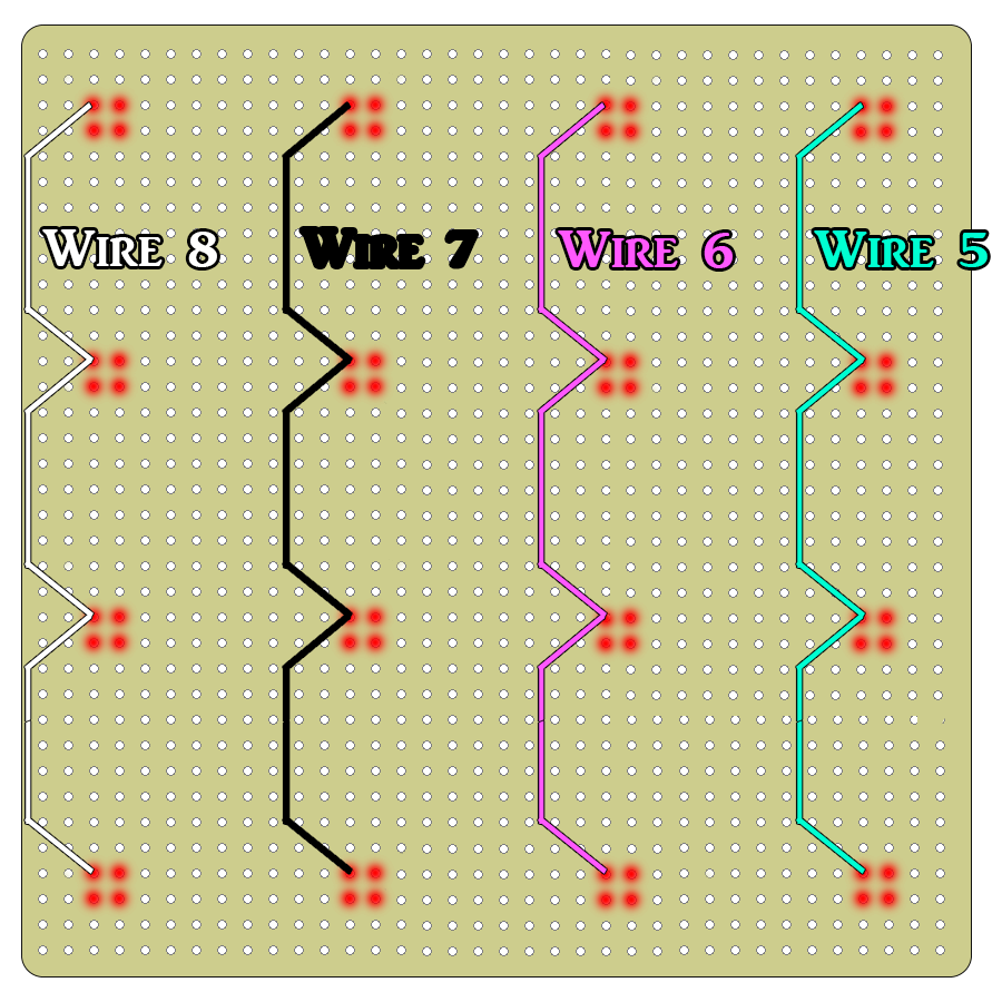
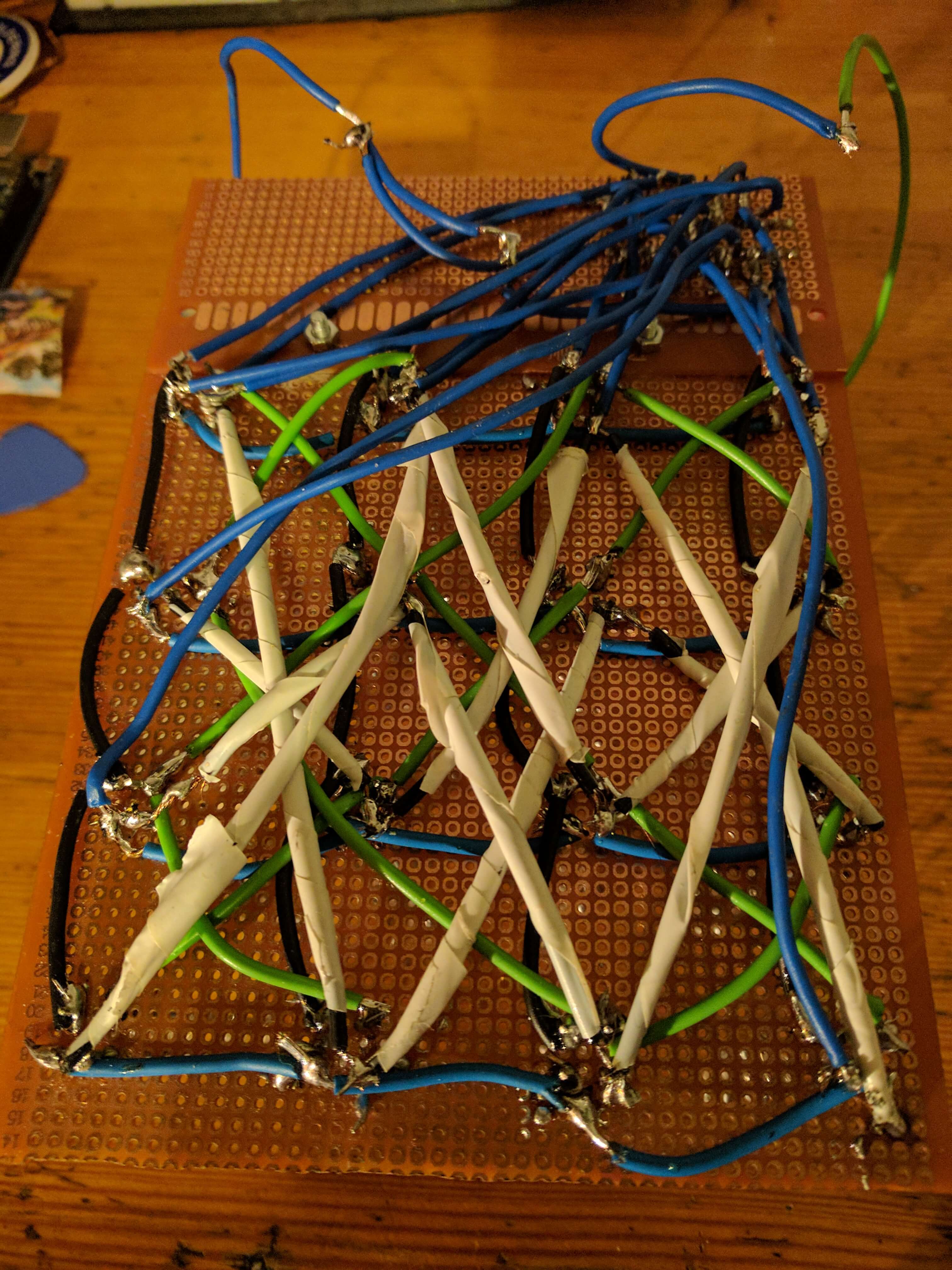
One of last things we need to do is to soldier many wires accordingly to the following schemes:


Once this is done last thing remaining is to connect all wires to Arduino UNO according to these instructions:
| Wire Number | Arduino Pin | AVR Pin |
|---|---|---|
| 1 | Digital 2 | Port D – Pin 2 [PD2] |
| 2 | Digital 3 | Port D – Pin 3 [PD3] |
| 3 | Digital 4 | Port D – Pin 4 [PD4] |
| 4 | Digital 5 | Port D – Pin 5 [PD5] |
| 5 | Digital 6 | Port D – Pin 6 [PD6] |
| 6 | Digital 7 | Port D – Pin 7 [PD7] |
| 7 | Digital 8 | Port B – Pin 0 [PB0] |
| 8 | Digital 9 | Port B – Pin 1 [PB1] |
| 9 | Digital 10 | Port B – Pin 2 [PB2] |
| 10 | Digital 11 | Port B – Pin 3 [PB3] |
| 11 | Digital 12 | Port B – Pin 4 [PB4] |
| 12 | Digital 13 | Port B – Pin 5 [PB5] |
| 13 | Analog 0 (Digital 14) | Port C – Pin 0 [PC0] |
| 14 | Analog 1 (Digital 15) | Port C – Pin 1 [PC1] |
| 15 | Analog 2 (Digital 16) | Port C – Pin 2 [PC2] |
| 16 | Analog 3 (Digital 17) | Port C – Pin 3 [PC3] |
Personally, instead of the whole Arduino I use only atmega 328p-pu controller, two capacitors 22nF and 16 MHz crystal. Do not forget when choosing solderless breadboard that these components must also be included on the board. Unfortunately I have forgoted about this and had a little bit more work on enlarging solderless breadboard and appropriate placeing wires.

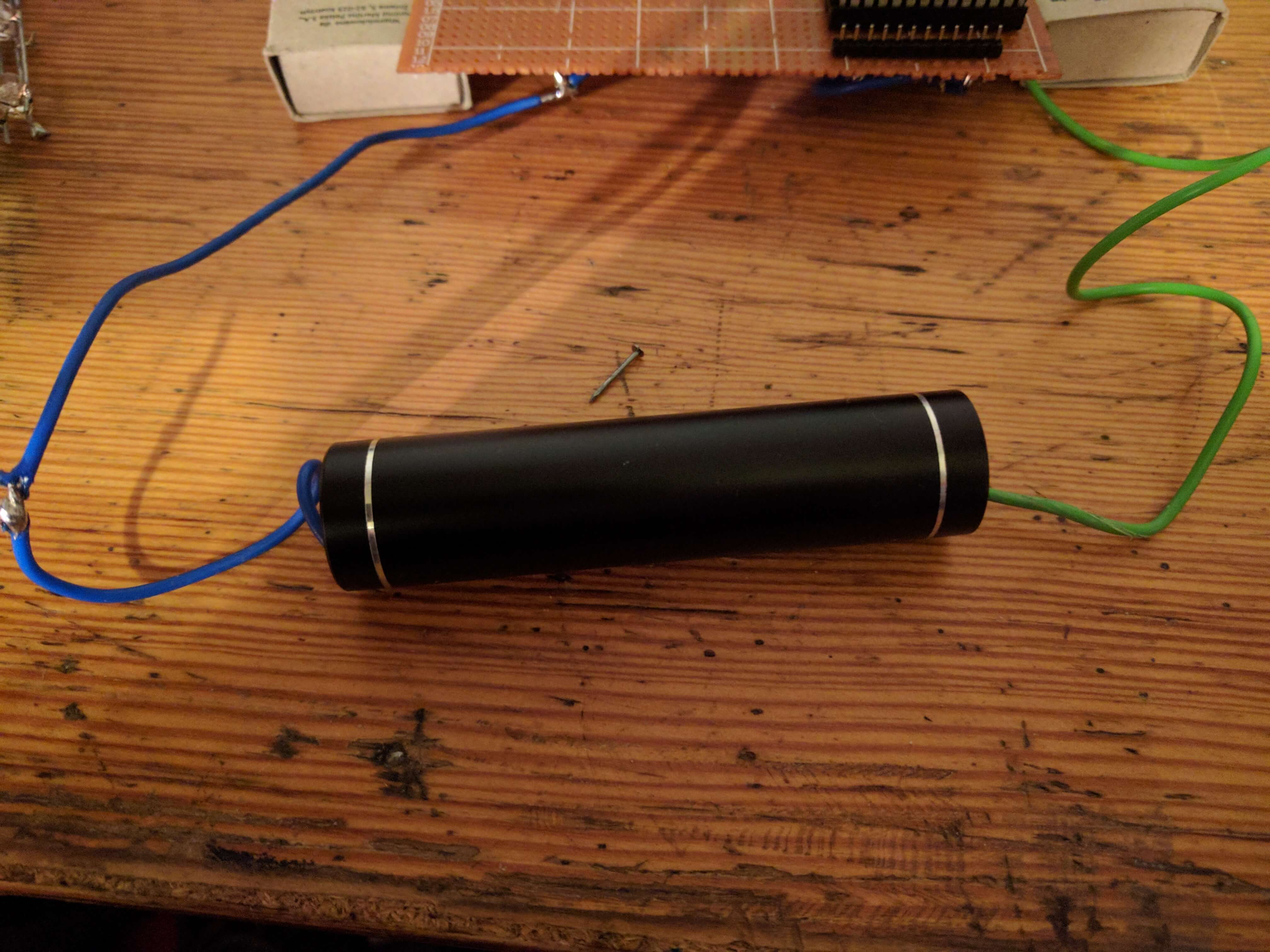
We suooly our circut with voltage of 3-5v. Personally I use 18650 battery with my home made basket from the remenants of charger to just these batteries.
For Atmega 328p-pu, we can upload the following sample programs or create our own. Before that, however, we need to download the appropriate library created by Asher Glick – the person thanks to it is possible to create this kind of led cube.
//Draw Led
#include "cubeplex.h"
int color = red;

void setup() {
  // initilize the cube display
  initCube();

  // how many secconds until continuePattern is set to false
  animationMax = 10;
}
void loop() {
  randomLed();
}
void randomLed(){
  continuePattern = true;
  int animationSpeed = 100;
  while (continuePattern) {
    int xpos = random(0,4);
    int ypos = random(0,4);
    int zpos = random(0,4);

    drawLed(color,xpos,ypos,zpos);

    flushBuffer();
    clearBuffer();
    delay(animationSpeed);
  }
}
//Draw Box
#include "cubeplex.h"

void setup() {
  //initilize the cube display
  initCube();

  // set the number of seconds until continuePattern is set to false
  animationMax = 10;
}
void loop() {
  bigBlueBox();
  tinyGreenBox();
}
void bigBlueBox() {
  continuePattern = true;
  draw(blue,0,0,0,3,3,3);
  flushBuffer();
  clearBuffer();
  // do nothing while the pattern continues
  while(continuePattern);
}
void tinyGreenBox() {
  continuePattern = true;
  drawBox(green,FULL,1,1,1,2,2,2);
  flushBuffer();
  clearBuffer();
  // loop until the pattern is done
  while(continuePattern);
}
//Draw Hollow Box
#include "cubeplex.h"

int color = red;

void setup() {
  // initilize the cube display
  initCube();
  // set the number of seconds each animation should run for
  animationMax = 10;
}
void loop() {
  pulsingCube();
}
void pulsingCube() {
  continuePattern = true;
  int animationSpeed = 100;
  while (continuePattern) {
    for (int i = 0; i < 4; i++) {
      drawHollowBox(color,0,0,0,i,i,i);
      flushBuffer();
      clearBuffer();
      delay(animationSpeed);
    }
    for (int i = 0; i < 4; i++) {
      drawHollowBox(color,i,i,i,3,3,3);
      flushBuffer();
      clearBuffer();
      delay(animationSpeed);
    }
    color=nextColor(color);
  }
}
//Draw Box Outline
#include "cubeplex.h"

int color = red;

void setup() {
  // initilize the cube display
  initCube();
  // set the number of seconds each animation should run for
  animationMax = 10;
}
void loop() {
  pulsingCube();
}
void pulsingCube() {
  continuePattern = true;
  int animationSpeed = 100;
  while (continuePattern) {
    for (int i = 0; i < 4; i++) {
      drawBoxOutline(color,0,0,0,i,i,i);
      flushBuffer();
      clearBuffer();
      delay(animationSpeed);
    }
    for (int i = 0; i < 4; i++) {
      drawBoxOutline(color,i,i,i,3,3,3);
      flushBuffer();
      clearBuffer();
      delay(animationSpeed);
    }
    color=nextColor(color);
  }
}
//Draw Box Walls
#include "cubeplex.h"

int color = red;

void setup() {
  // initilize the cube display
  initCube();
  // set the number of seconds each animation should run for
  animationMax = 10;
}
void loop() {
  fountian();
}
void fountian() {
  continuePattern = true;
  int animationSpeed = 100;
  while (continuePattern) {
    for (int z = 0; z <= 3; z++) {
      drawBoxWalls(color,1,1,z,2,2,z);
      flushBuffer();
      clearBuffer();
      delay(animationSpeed);
    }
    for (int z = 3; z >= 0; z--) {
      drawBoxWalls(color,0,0,z,3,3,z);
      flushBuffer();
      clearBuffer();
      delay(animationSpeed);
    }
    color=nextColor(color);
  }
}
//Draw Line
#include "cubeplex.h"

int color = red;

void setup() {
  initCube;
  animationMax = 10;
}
void loop() {
  planarSpin();
}
void planarSpin() {
  continuePattern = true;
  int animationSpeed = 50;
  int spinsPerColor = 5; // a spin is actually half a revolution
  while (continuePattern) {
    int x = 0;
    int y = 0;
    for (int i = 0; i < spinsPerColor; i++) {
      for (int x = 0; x < 3; x++) {
        drawLine(color,x,0,0,3-x,3,0);
        drawLine(color,x,0,1,3-x,3,1);
        drawLine(color,x,0,2,3-x,3,2);
        drawLine(color,x,0,3,3-x,3,3);
        flushBuffer();
        clearBuffer();
        delay(animationSpeed);
      }
      for (int y = 0; y < 3; y++) {
        drawLine(color,3,y,0,0,3-y,0);
        drawLine(color,3,y,1,0,3-y,1);
        drawLine(color,3,y,2,0,3-y,2);
        drawLine(color,3,y,3,0,3-y,3);
        flushBuffer();
        clearBuffer();
        delay(animationSpeed);
      }
    }
    color = nextColor(color);
  }
}
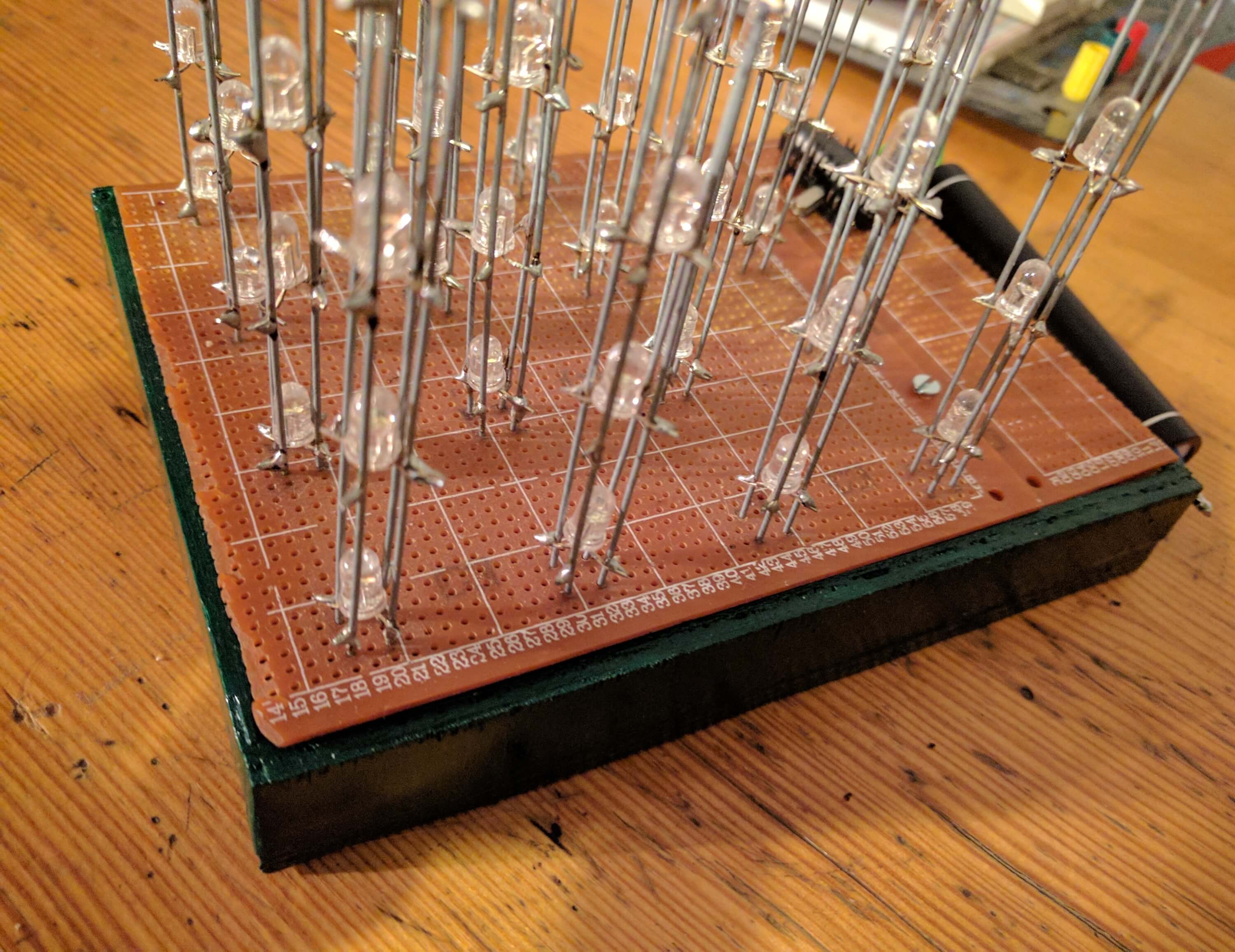
The whole project in my performance is as follows:
If we have a little bit more time we can create stand for our project:
For those who do not like to solder by hand hundreds of wires I prepared project in Eagle which allows to create printed circuit board: